Chapter 53 or Getting a little Stude V8 ready for prime time….
Well, After replacing all the valve springs in the Turbo Champ six motor and getting her back on the road, I realized that the engine is showing some signs of its age. After all, it was used aggressively on the salt and has been running on propane for 10 years. I needed to have a fallback engine to have fun with! I fell into a 55′ 224″ motor and overdrive transmission (and Scout top shifter mechanism) a while back. The conversion to top shifter was documented in an earlier chapter, and now I will show my journey with the 224″. These motors were only used a couple years before Stude decided that they would continue only with the 259 and 289. The difference was the stroke only. By this time, the valve trains were the same on all the v8’s, though the combustion chambers and CR’s varied depending on the application. Stude actually used a lot of the 224’s in trucks! In looking at these motors, and after racing a destroked one on the salt, I have respect. The crank overlap may be more than any other v8 because of the short stroke, and that, coupled with being forged, makes it virtually indestructable. I have spun the racer to 9000 rpm!
My plan is to use “55” heads, steel shim head gaskets, Pertronix/old Delco distributor, 3 ohm coil,
8mm resistor wires, stock flywheel with 10% lightening, stock T86 overdrive tranny with top-load conversion, 3.43:1 8.8” Ford diff with 29” tall tires.The differential ratio might need to change. I can get gear sets up into the mid 4’s without problems. The 182″ v8 in the salt car had 4.11’s and was still pretty happy on the street with a few revs….. This should have more torque lower down than that car and is lighter by 1200#. The carb could either be a Stromberg WW (1 7/16 bore) or a small base R4371 Holley 2 barrel (1 9/16 bore) with a 1” spacer. Stock intake manifold. I plan to fill in the valleys in the lifter chamber with resin and remove casting flash to ease drain back. Lifter clearance seems just right but lifters have lost their domes. Oil pump clearances are good. New oil pressure relief valve kit. Fiber timing gear looks like new. I might enlarge the drain back hole at the back of the valley (per Dick Datson). Making my own windage tray. The cam I have looks to be in bad shape. Modern timing cover seal. The roadster is for street use and weighs about 1900#. For headers, I will follow Digger Dave’s directions (PowerMax program). Which carb? Stock cam or R1?
As I dismantle it, I notice minimal piston or cylinder wear. Minimal sludge in the engine, and the crank & rod journals look good. The lifters are dished and the hardening on the cam lobes is deteriorating. The cam journals look fine.


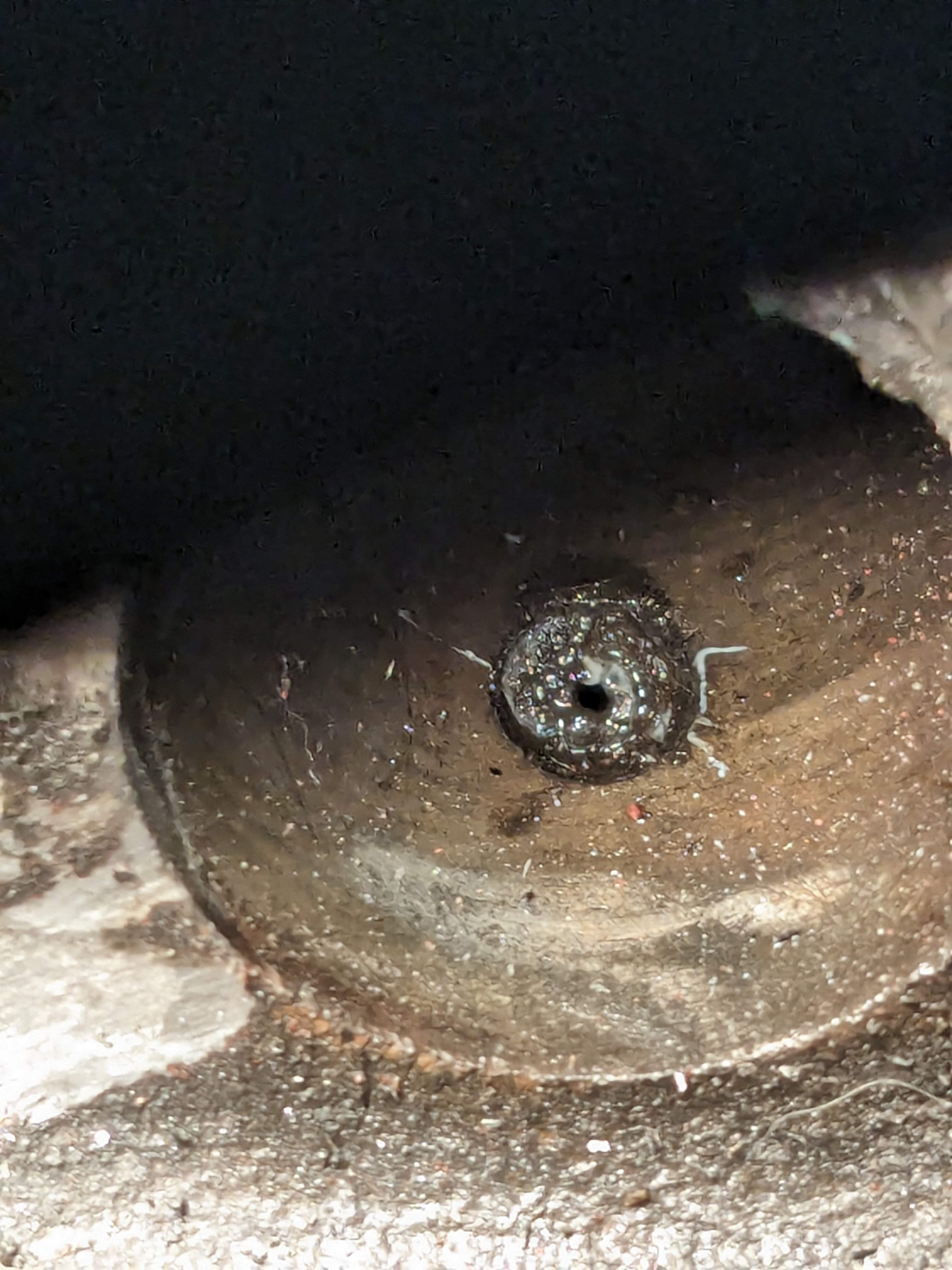
Down in the valley, with plenty of casting flash. On the far right is the drain-back passage near the gear on the cam which drives the distributor. I will elongate that hole and radius everywhere there is casting flash. You can see where I will “flood” the valley with resin to minimize top end oil retention. You can also see the lifter bore oiling passages, which I may block off.
I have ordered a ridge reamer for the minimal ridges. I have a straight hone. I will use this with WD-40 and a fairly gritty stone to match new cast iron rings. I will then briefly use a ball type hone, then thoroughly wash the whole block of scrapings and wd-40 in the bores and 69 years of groat in the coolant passages. To remove the freeze plugs, drill a hole in it, tap the hole and screw in a bolt. Use the curved end of a crow bar to easily lever out the plug!


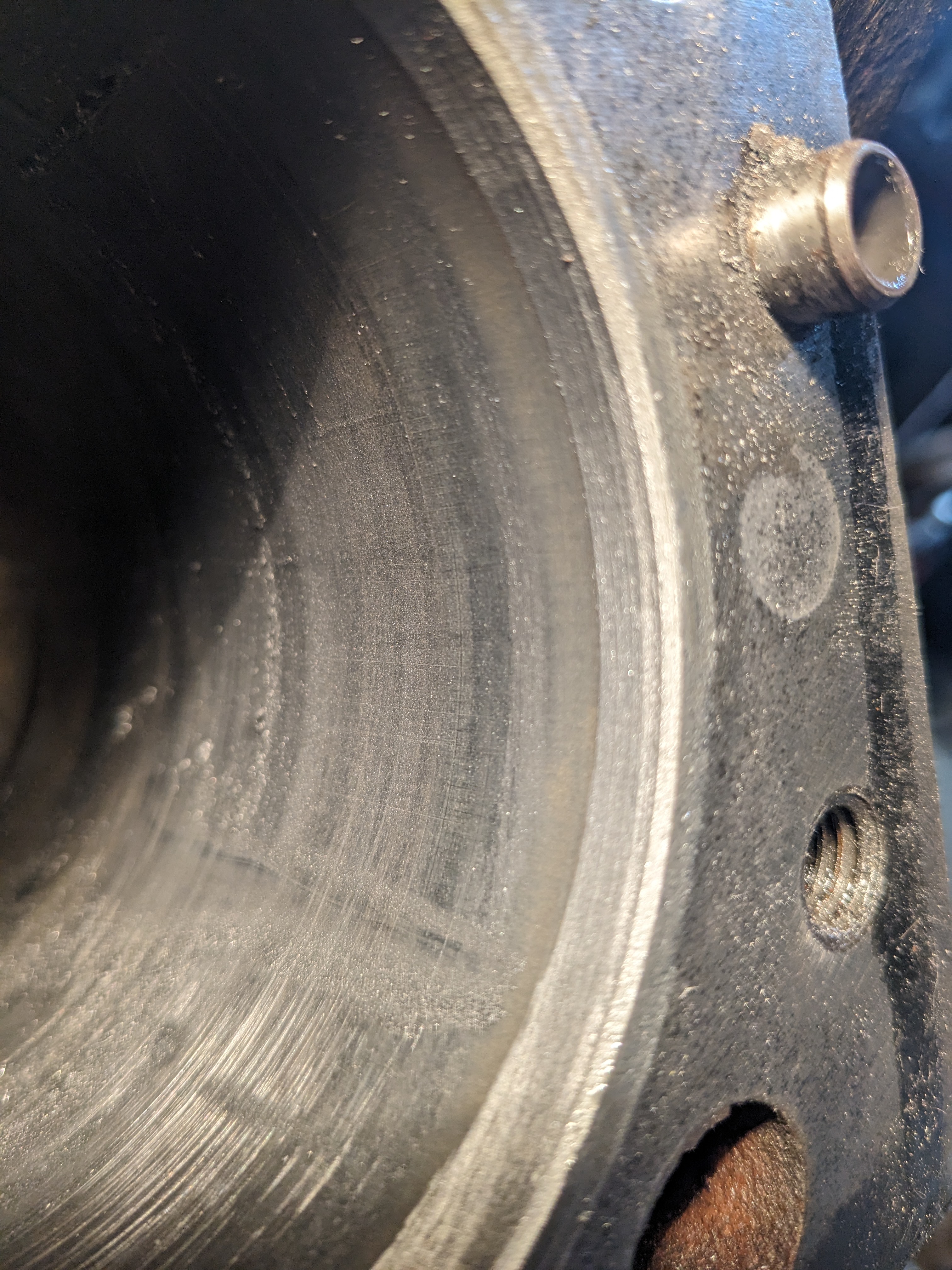
Notice that I extended the drain-back hole, smoothed its edges and ground down the casting flash around the lifter bores.

Crank journals actually look pretty good and crankshaft spins easily.

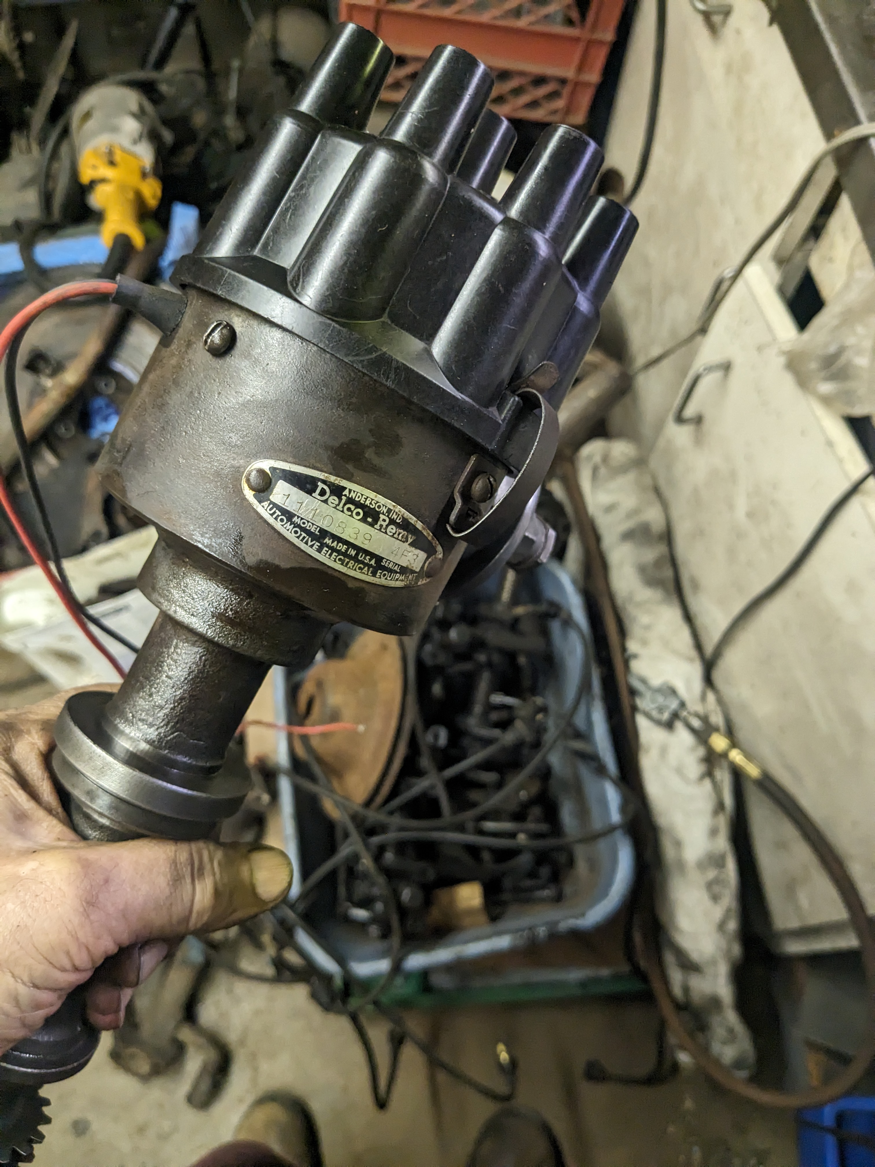
Cleaned up an early Delco distributor #1110839 Cap # DR427 and installed a Pertronix lobe sensing pickup.

This is a Holley 4371-A carb from a 70’s Mopar v8. The base is a little splayed out from the stock Stromberg WW and has a slightly bigger bore. In 56′ the factory was feeling the HP race and recommended using a small four barrel, so I’m guessing that with better ignition, cam and exhaust this carb may be just the ticket. Will make a 1″ spacer/adapter to fit. Will teach my Tools4Teens crew how to rebuild this carb.
To decrease the amount of oil getting stalled in the top of the motor, and increase oil pressure loss due to worn lifter bores, I decided to follow the suggestions made years ago by Dick Datson and Ted Harbet. Dick described actually plugging the lifter bore oil passages completely with set screws. Ted placed roll pins in each 3/32″ passage. I first chased all the 3/32″ holes with a drill bit. Then, using a special tool which I made on the lathe and a little grease to hold the roll pin on it, I was able to start the pins in the holes and finish them in 0.5″ with a drift. There is still a passage through the center of the roll pins which will allow perhaps half as much oil to get through….


Struck across the orifice with a chisel to broach the hole which should help keep the pin inside. Cleaned up the original push rods from the 224″. Will compare with pushrods from the 55″ heads for length. Will also check the oil passages in the rocker assembly to see if they are the same, since they are from a later 289″ full flow motor made in late 1964.

Spoke with Phil Harris and Digger Dave Molnar about cam selection. I will be using the R2 cam. Will order it, new lifters and stock bore cast iron rings today. Next comes ridge ream and cylinder hone!
First, the ridges above the top ring must be reamed down to facilitate piston insertions and proper honing. I used WD-40 and chucked the Lisle ridge reamer in my drill. This brought most of the ridge down until it was not detected with my fingernail. Some areas persisted, so using a 13/16″ box wrench I brought the reamer blade over to these areas and used the reamer by hand to carve down the remaining ridge.

Here is a ridge at the top of the cylinder….
Here is the cylinder after ridge removal

Here is a dirty Lisle ridge reamer after reaming. Next comes gradually tightening the lateral tension as you rotate the reamer, first with the drill and WD-40 and then use on high spots with the box end wrench.


Honing is next. First with a straight edged three prong reamer and then with a “dingle-ball” hone, going up and down just fast enough and turning the drill just fast enough to get a cross-hatched pattern.

So, now the block went out for a good bath at the car wash. It took $8 worth of tokens to flush the coolant passages till clear water came out, but no wires or chunks of rust really came out. Then back to the ranch for some drying and steel wool after laboriously getting it back on the engine stand….

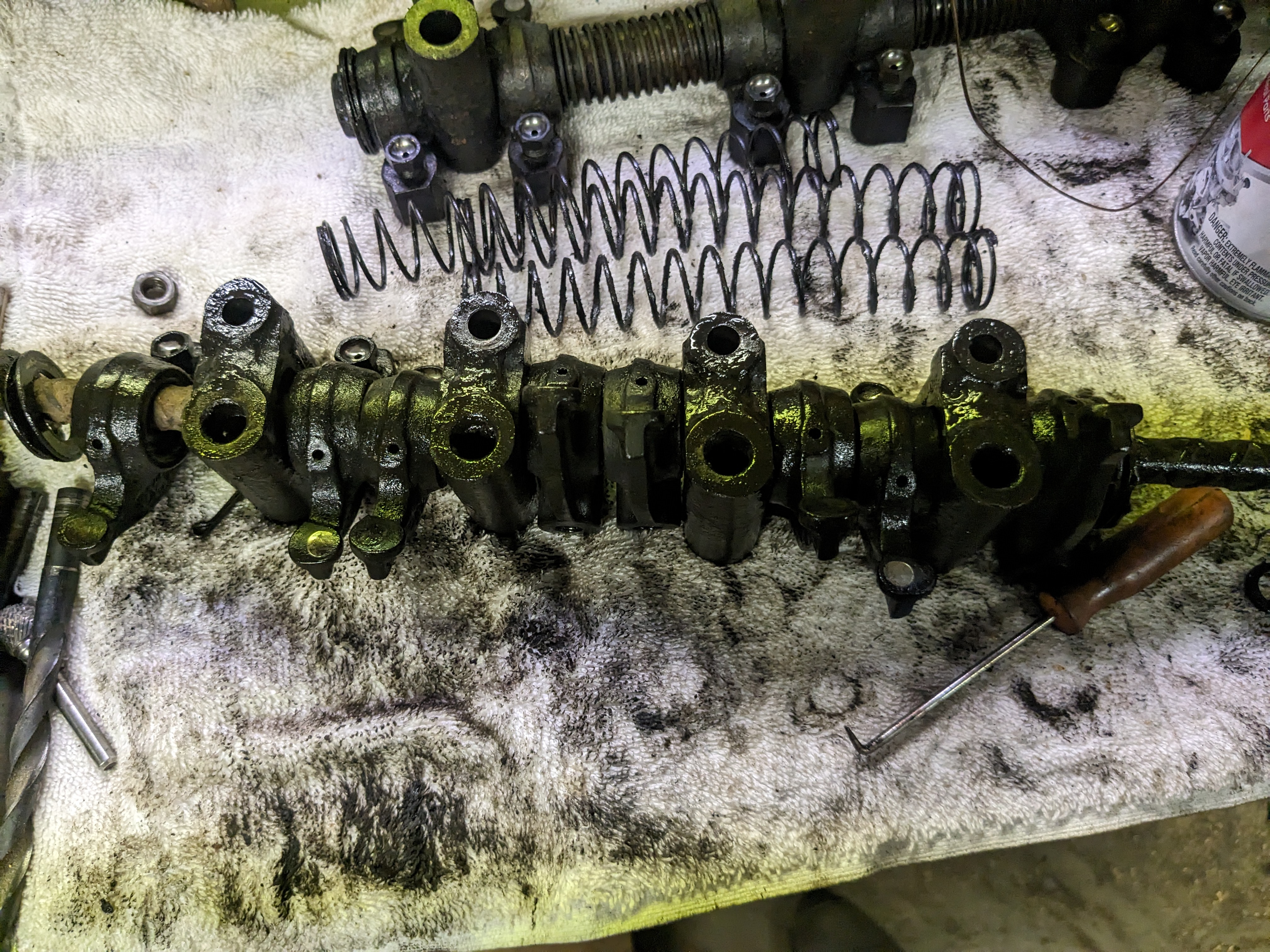
Looking at the valve trains from the 224 and 289 which I have. Normally, the orifices in the rocker shaft of a 224 are big and let more oil into a loose top end than the later post 61′ motors. Turns out that someone swapped in later rocker shafts on this 224! The holes I measured in the rocker shafts going to the rockers seem to be 5/64″ (0.078″). The push rods are the shorter ones which must be matched with the pre-61 rockers to maintain the right geometry. The later rockers are drilled differently too, so the oil must hop over the top of the adjusters to get where it is going rather than “thru” the adjuster.


The 224 rocker arm assembly was in much better shape in terms of rust and wobble, so I will take them apart and clean out all the oil passages, then use the shorter pushrods and matching rocker arms. The rather pricey Glyptal paint ($72/pint) has arrived, so while it is drying I will work on the assemblies….

Brake cleaner will remove it.


Two part epoxy was mixed and kneaded into the depressions/ low points in the lifter valley to prevent pooling of oil and promote return to the bottom of the engine.

Gently chasing the lifter bores with an old lifter welded to a 1/4 rod and some WD-40 after cleaning the works and removing some over-paint drips.

More on the carb situation. I took the carb manifold gasket from a Stromberg WW and the same from the Holley two barrel and created a two piece 1.5″ spacer/adapter out of multi-ply plywood which would fit on a late type two barrel intake manifold. With proof of concept in hand, I will eventually reproduce it out of aluminum. The bottom piece has smaller bore holes which match the WW. The top of it will splay open to match the Holley bore. In the top of that piece I will have countersunk holes allowing coarse barrel head allen type screws to fasten it to the manifold. The top piece will have studs threaded in to accommodate the Holley base. The two halves will have allen head screws countersunk in to affix them together. Using the two gaskets I should have adequate thermal isolation.


After bragging about my adapter, my buddy told me that he had a complete, done manifold/adapter/carb setup he wouldn’t be needing! I might buy that from him…..

Next is to completely disassemble the rocker arm assemblies and clean out all the oil passages. Here is the first step on the driver’s side. The shaft looked good except one rusty spot where only the spring is located. The areas beneath the rocker arms themselves had a mirror finish without any signs of wear. Hopefully the other bank will look this good! The hole supplying the rockers is in the back of the right bank and the front of the left bank, making the assemblies potentially interchangeable, as are the heads, side to side.

To keep every piece in its place with proper orientation, I threaded them all on to a rod as I took it apart. Do I polish or lightly sand the rocker pads where the valves sit against the rocker?

Ultimately, after watching a number of videos, I decided it would be ok to clean up the surfaces of the rocker pads. First I used the side of a rather fine abrasive wheel I set up for sharpening TIG electrodes with some WD-40 for lube. After getting out the scuff marks I used a barrel sander in the drill press to give it a finer finish and make sure everything was square to the axis of the rocker shaft. All the holes in the shaft were probed and cleaned, as were all the passages in the rockers. Everything was put back together with assembly lube.


Wondering if I could grind each rocker as highlighted to lighten them (they are very heavy!) using a postal scale to standardize their weight……?
Heard back from Digger and found that Ted Harbit wrote about this…. Unless you have a full race motor, Ted found that there was minimal benefit to changing the rockers or making headers. I will just be happy with cleaned up rocker assemblies and stock dual exhausts. I cleaned up and will reuse the original bolts.

So, the next messy job was the oil pump. After degreasing and wirebrushing the outside, I took it apart and used the ultrasonic cleaner filled with heated Pinesol to bathe the pickup. Inspecting the rest of the pump I noticed no scuffing on the gear chamber walls, but did see some on the cover. Trying to wiggle the gears in situ, I could detect a couple thousandths movement, but I was happy. I put a plate of glass down on the workbench and then a piece of sticky-backed 400 grit sand paper. Then I sprayed it with WD-40 and started sanding in a processional figure 8 movement for a long time. Then, after getting most of the scratches out, I added valve grinding compound to the WD and continued till I had a pretty smooth finish. Still not perfect, but pretty fair. With a straight edge across the top of the chamber there is less than 0.007″ clearance when the now reconditioned cover is in place. I was advised to put a 1/8″ hole between two teeth on the “being driven” oil pump gear. This was to assure that the dummy shaft would never lack lubrication. It was easier to drill than I had anticipated. I chased the inside of the gear with a 1/2″ drill to insure that any swarf from drilling was gone. I used compressed air over the whole gear after that. The cover was then bolted back on after filling the pump up with assembly lube. I brought the cover screws to about 10 ft/lbs after a dab of Loctite blue on each one tightening in a cross hatch pattern a bit at a time.


Next came a task I was not looking forward to, but turned out to be a sort of soothing, repetitive one. I removed all the rings, then soaked the pistons/rods in Simple Green for an hour and then chipped away at cleaning out the heat containment grooves just under the piston crowns with a combination of picks and thin screwdrivers. Easier was using broken rings to clean out the compression and oil grooves. I used WD-40 for this and for scrubbing the remaining piston with 3M scouring pads and a brass wire brush. I cleaned the piston tops as well and used some 400 grit paper and WD to get down to the original milling marks. I didn’t polish these any finer than that.

The pistons in general showed no wear grooves, but did show some slight nicks around the perimeter of some crowns. I plan to use some 400# to slightly chamfer these areas. If left alone, these are areas of possible detonation. Here is number one before…. Note that the heat containment groove is totally filled in with grot!


Four hours later….

Zoom in to see grooves after….
Ready to check end gap on rings in each bore. To do this, the ring must be pushed EVENLY to the lowest area of ring excursion in each bore and gap measured with a feeler gauge. False readings would result if the ring was not parallel to the bore. According to the manual, it should be between 0.008 and 0.016″ for the stock cast iron rings. I made a “pusher” by marking the circumference of a piston on a piece of plywood and cutting it to size very carefully. I then added a handle…..


Subsequently, I was able to determine that the bores could be used with the new cast iron piston rings. Then, after copious lube, I was able to install the rings and then attach the pistons/rods in place on the crank.


Noting the correct torque settings for main caps and rods, it was all set to specs.

Now I am putting back in all the little plugs etc. to seal the oil and water passages. I filled the oil pressure control chamber with set-up lube and screwed in a new piston and spring. I lubed up the shim cover holding in the cam and torqued that to 15 ft#. Then came the very dirty job of leaning up the timing cover…..


Once the timing cover was clean I decided to dispense with the felt seal through which the balancer snout goes….and leaks. This is replaced by a sleeve on the snout which matches a modern seal in the cover. The seal is pretty close to the right size of the cover after a thin sliver of plastic shim is used to center it. This is a technique developed by the famous Ted Harbit. I have cleaned up the harmonic balancer and timing wheel so that i will actually be able to see the marks on it…..
I should add that the 224″ timing wheel is DIFFERENT than the bigger displacement wheels. It has the number 536563. The keyway is designed to advance timing at the factory on the 224″. Here is the spec card on the cam:


I turned my attention to the pulleys which I sandblasted/polished and painted.

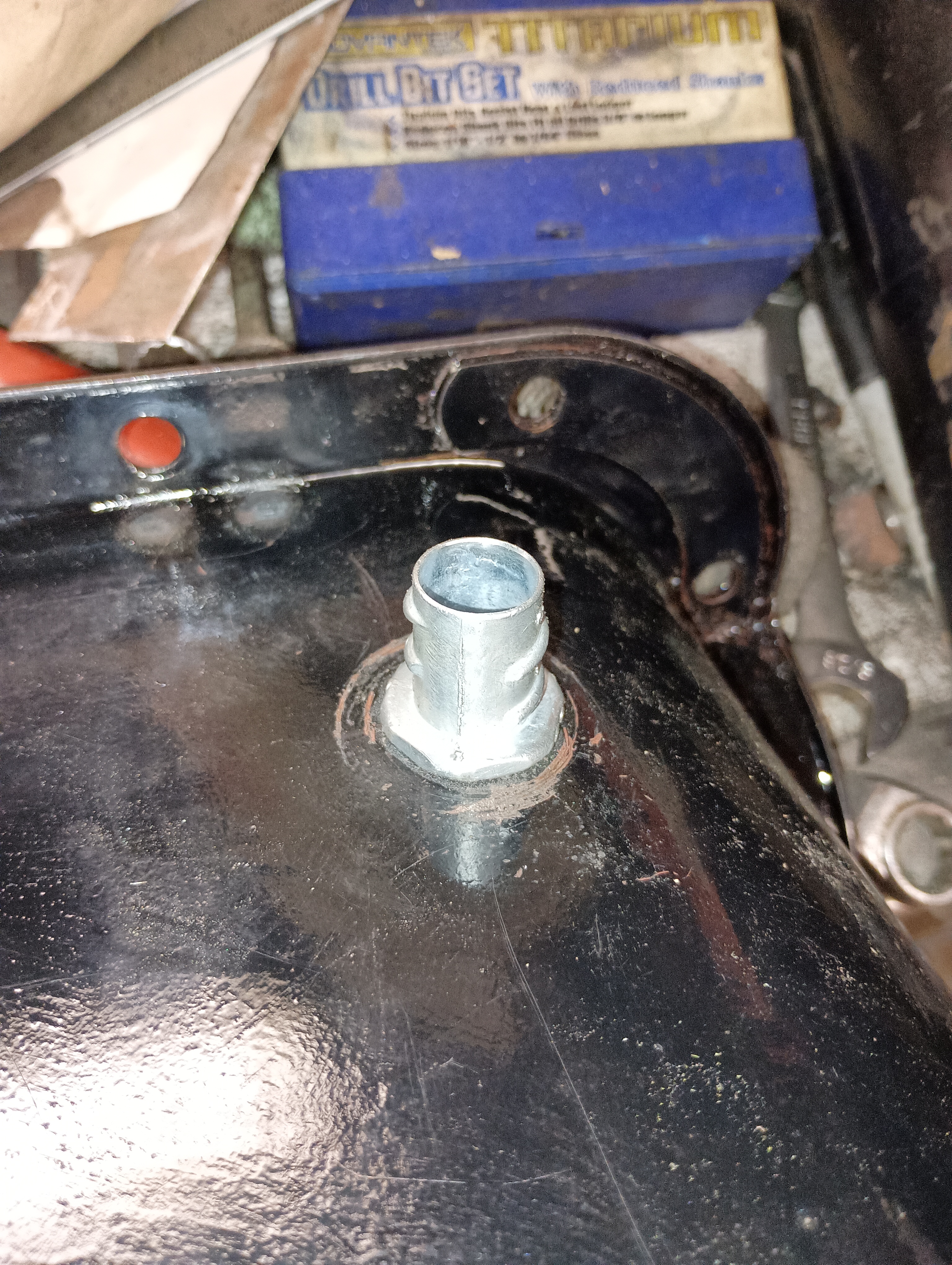
Today I will continue cleaning crud off the oil pan and banging out the dents. I am planning on adding some pipe flanges on each side to dump upper end oil directly into the pan.

Now is time to think about crankcase ventilation…. I am planning to put a breather on each valve cover. Hopefully the filtered air will go down through the heads/pushrod tubes into the lifter chamber and than mix with the updraft out of the oval hole at the back of the chamber coming up from the crankcase. There is also updraft coming from the crankcase thru the timing cover and into the tower usually used to put oil in the motor. That oil cap will be sealed.


Sealed off oil cap with rubber O-ring no longer a crankcase breather.
An outlet will be plumbed in which will “T” with the former road draft tube (which exits through a baffle in the lifter cover) on one side and then, before going into the intake manifold base on the other will be conducted, first through an oil trap and then through a PVC valve. The flange on the valve will face towards the manifold. Not sure whether I will need to add drains in the posterior parts of each valve cover down into the oil pan, as these motors can develop top end oil buildup from sustained high rpm.
Block off plate was made for the mechanical fuel pump. Since this is a direct connection to the crankcase, it may be drilled as a drain for the valve covers, obviating any more holes in the oil pan….

I have installed 6 disc type core plugs with blue rtv after wire brushing the grooves in the holes. I also aligned the marks on the timing gear and crank gear. I previously had added a washer and woodruff key to the front of the cam and torqued down the thrust plate to 20 ft#. The motor is now set at firing position for #6 cylinder. When I insert the distributor, the rotor should be pointing straight backwards. I am slowly getting years of grot off of the valve covers. Oil pan is finally clean and painted.


A little hard to see, but the bottom crank gear has a “0” on two adjacent teeth. Even harder to see is that the upper timing gear has a “0” on one tooth between the bottom teeth.
In one of Dick Datson’s books, I found a pattern to duplicate a windage tray for an R2. I drew it out life-size and then traced it on to a piece of sheet metal. Next came the tedious job of cutting it out on a band saw. A little bending and scrubbing will get it ready to tack into the oil pan. A second piece will fit over the oil pump area.


Here is an example of an R-series tray which I am copying……. The one on the right has a deeper sump to hold more oil and pull oil further out of the way of the whirling crank. Notice the hole on the side of the pan for crankcase ventilation. I am going to place drain-back ports from the valve covers in this location on both sides.


At sustained higher speeds too much oil can hang around the top end. Half inch electrical conduit connectors should be effective in the valve covers and the upper rear pan sides, near the site used on the R-series for a vent.


The crankcase vents out through the “A” elongated hole I made in the posterior lifter chamber and “B” the lower timing cover. Pressure continues through the pushrod tubes into the valve covers, also out through the lifter chamber cover (old road draft tube). These contributions all dump into a “T” just before the oil catch can. This dumps into the PCV valve and then into the intake manifold. I am not clear on whether the valve covers should be just vented with open breathers near the fronts or closed caps with tubes up into the air filter.


Phil Harris at Fairborn Studebaker had some made. I ordered two for $38. DONE! He will send along 8 of those grommets used to hold down the valve covers.
Today I sealed the drains from the valve covers with two part epoxy and mounted a couple K&N valve cover breathers. These might be changed to sealed breathers….

I have generously lubed the new lifters and slid them into place. I can’t imagine a better fit, and expect minimal slop in the bores. I have inspected the shorter pushrods for straightness and tip wear. A master mechanic friend pronounced them to be fine…

There are three lengths of head bolts used to fasten the heads to the block. The holes into which these go are 14TPI 7/16″. The bolts were all wire brushed and careful attention was paid to their condition as far as underneath the cap and the threads as well as any nicks or signs of stretching. Some suggest a washer under each to further standardize the torque settings. I will use a grade 8 washer and some motor oil on each and set torque to 55#. The steel shim head gaskets were all treated with copper coat spray and the bolt holes chased with a tap. The bolt holes on a Stude V8 do not connect with the water jacket, so no sealer will be required.

The head markings show #1557570.

This has a combustion chamber measuring 54.5cc. That was used in 63-64′ R-1 motors. Look up tables indicate that with a steel shim gasket the C.R. is 10.25:1……… BLATT!
| 1557570 | 1557571 | 63-64 | Std | 9.00:1 w/cupped pistons & Shim Head gasket(1545072) | 10.25:1 with flat top pistons & shim gasket (1545072) | 54 cc | Standard R1 heads |
The valve covers have been primered and painted with a yellow not unlike a factory color from the 50’s. I used some permatex to fasten the valve cover gaskets to the valve covers.

Now bolting and torqueing down heads. Broke one rocker shaft support stud at 18 ft# and had to reproduce. This time used a grade 8 bolt!


So, not to beat a dead horse about sparkplugs in Studes, but after reviewing the SDC tech forum and racing Studebakers, I still don’t have a clear understanding of recommendations fitting my situation. With an R head (1557570) from a 63-64 vehicle, flat top pistons, Pertronix, MSD coil, and a steel shim head gasket, I will be running about 10.25:1 CR. I’m seeing recommendations for 3/8″ reach plugs (as opposed to 7/16″) which would leave threads exposed in the head and shrouding of the tip. That CR suggests that I should be running about two heat ranges cooler as well. AC Delco R43S seems about right to me. That would be a “3” heat range. Would the “S” (extended tip) leave the center electrode a little less shrouded or allow it to bang into the head? I will stick a little piece of wax to the center electrode and turn the motor over when the plugs arrive.
Lifter cover was filthy, but now clean and primered.


Modified former road draft tube which will connect to an oil trap then a PCV valve, then the carb base.
I determined that pcv valves (2-9207) from 80’s Mopars are bent 90 degrees. I am going to try putting one in line with each of the 1/2″ vents I made in the valve covers as they go down to the spouts I made in each side of the oil pan. I am hoping this will promote one way air travel down into the crankcase which will continue upward through a different route back up to the inlet tract. They would be about where you see “1” in the diagram above.

These pieces worked after adding inner hoses to bring the I.D.’s up to 1/2″.
I safety wired all the main bolts and torqued the new special bolts with studs on top for the front part of the windage tray to 85 ft#. The top studs were torqued to 10 inch# .The front and rear windage trays seem to fit pretty well, but I will use a fiber-optic scope to check clearances. The oil pump clears the windage tray just fine. I loosened and placed blue lock-tite on each rod bolt before torqueing each to 53 ft#. The “Pal” nuts were omitted.
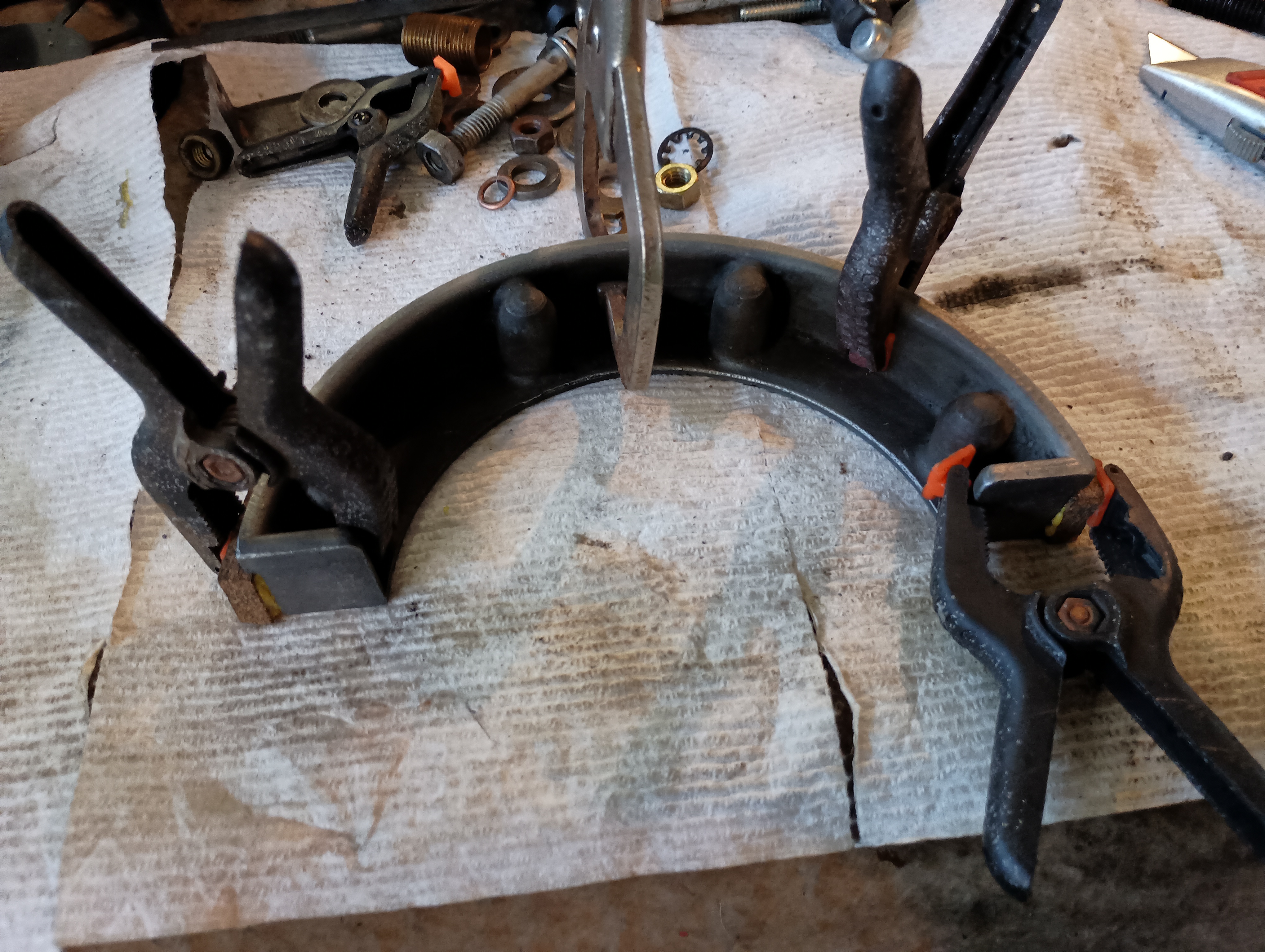
The time has come to start sealing up the bottom of the motor. Getting the cork strips in the front and back of the pan to stay in place is a trick. I made four studs to screw into the oil pan flange to locate the side pieces. I used a permatex hi tack compound to plaster these down, making sure the little tangs at the back would locate these pieces in continuity with the rear cork strip. That strip was jammed into position using some wood strips to keep it in the groove…..

The cork strip in front was a bit easier and I could use clamps

Getting the filler block and gaskets right at the front is crucial

I need two of these hold-downs….

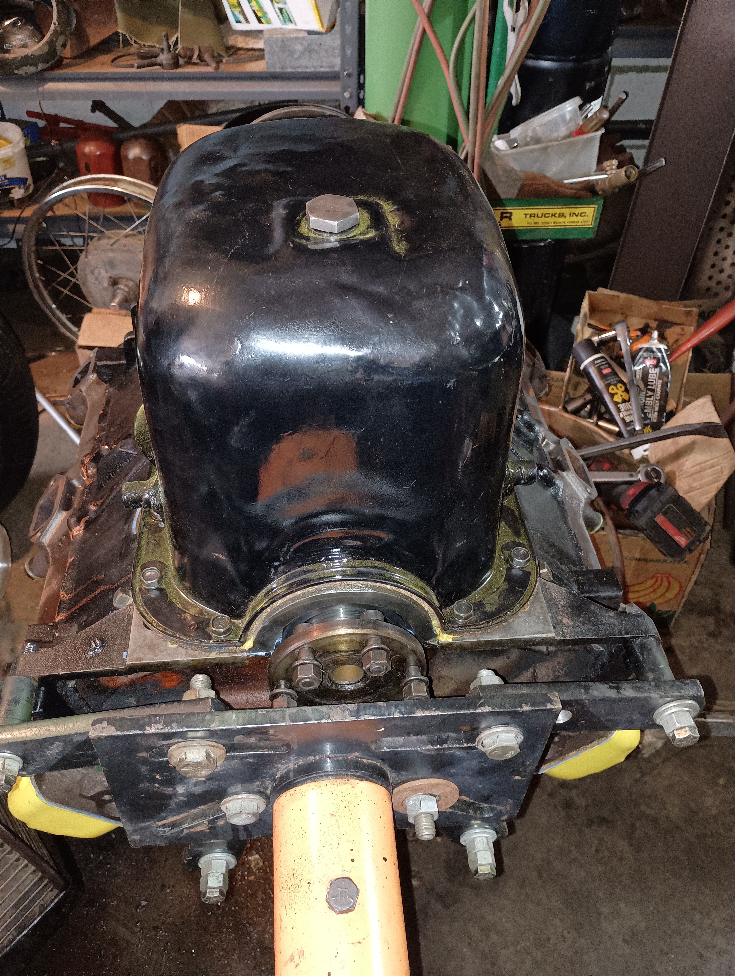
With attention to detail and careful sequential tightening, I was able to convince the oil pan and timing cover to settle into place. Slathering up the crank hub with lube, I used the hub tool from Phil Harris to slide the hub through the front seal. The timing cover was torqued to 13 ft#. The hub bolt was torqued to 130 ft# after greasing it up. Motor mounts are refurbished and I am preparing to sandblast the exhaust manifolds. I had to melt the brass nut off one of the studs.


My buddy helped me roll the motor over. After adding the heads, the motor got kinda top-heavy. I was then able to bring the motor to TDC on #1 cylinder and determine where the rotor should be in the distributor. I labeled the towers on the cap with their numbers so that I could place the plug wires. The plugs came and have been gapped to 0.035″ and installed.

I installed the drains from the rocker covers down to the oil pan on each side with pcv valves promoting travel in only one direction.

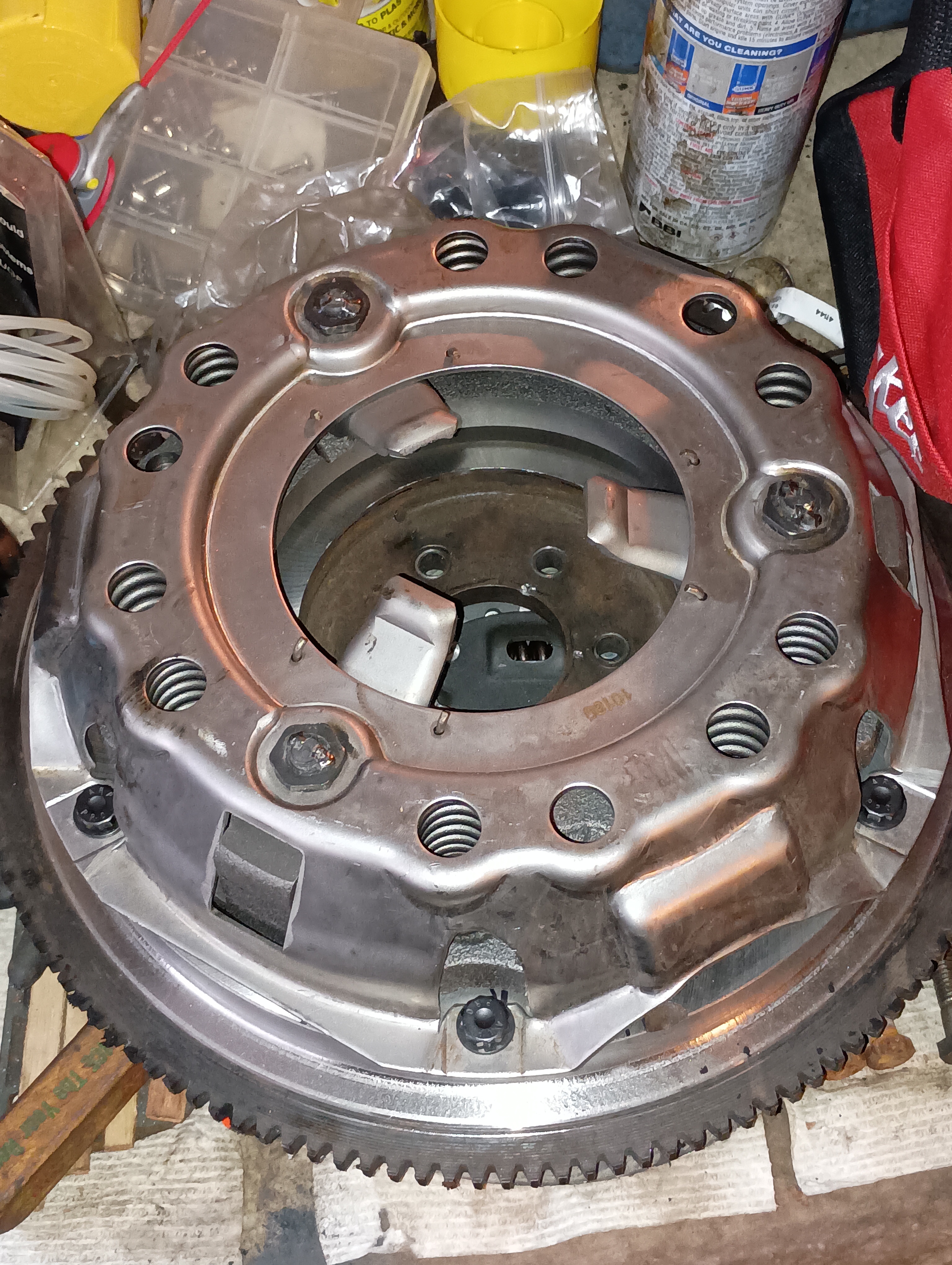
The clutch is back. New disc has kevlar pads and is a bigger diameter. The flywheel surface has been ground flat. Since the roadster is 1900# not 3300# I believe that a lighter flywheel will give better performance. The present one weighs 37#. There is room to remove quite a bit off the backside. Reviewing a flywheel discussion on Buick/Rover v8’s which are around 215 c.i. in MGB’s (2200#) I note flywheel trimming down to even 12#. I’m thinking that a 25# flywheel is conservative, but probably very safe.
I sandblasted a pair of exhaust manifolds, primered them and painted them before bolting them in place. Ultimately I expect to build some custom headers, but for now, these will direct the flames….

There are two types of water pump manifold…. They are shaped to accommodate the timing covers. One type has a water outlet with 4 bolts, the other 2 bolts. Water pumps seem interchangeable. I sandblasted a two bolt one, primered and painted it and bolted it all together using Hi Tack Permatex.

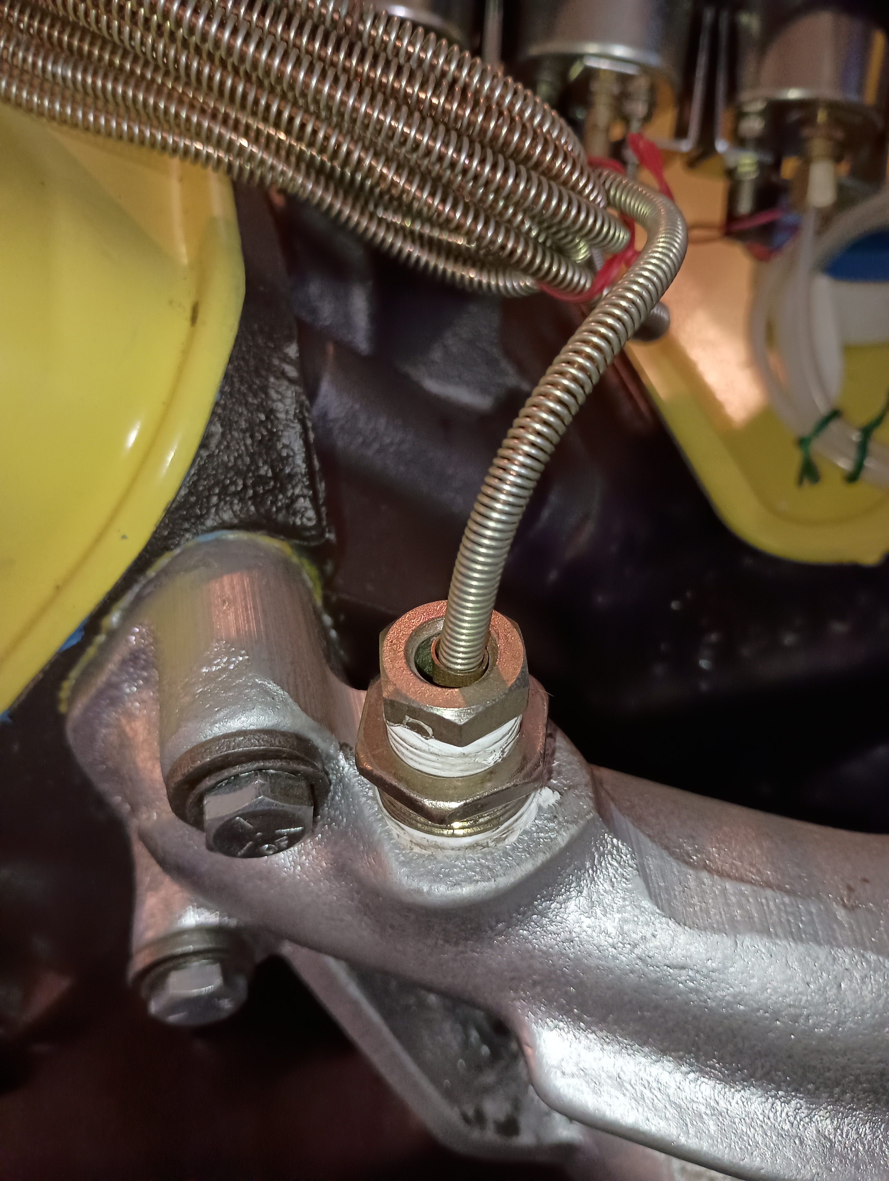
I used the heater outlet to plumb in a water temp sensor. The heater inlet was plugged.
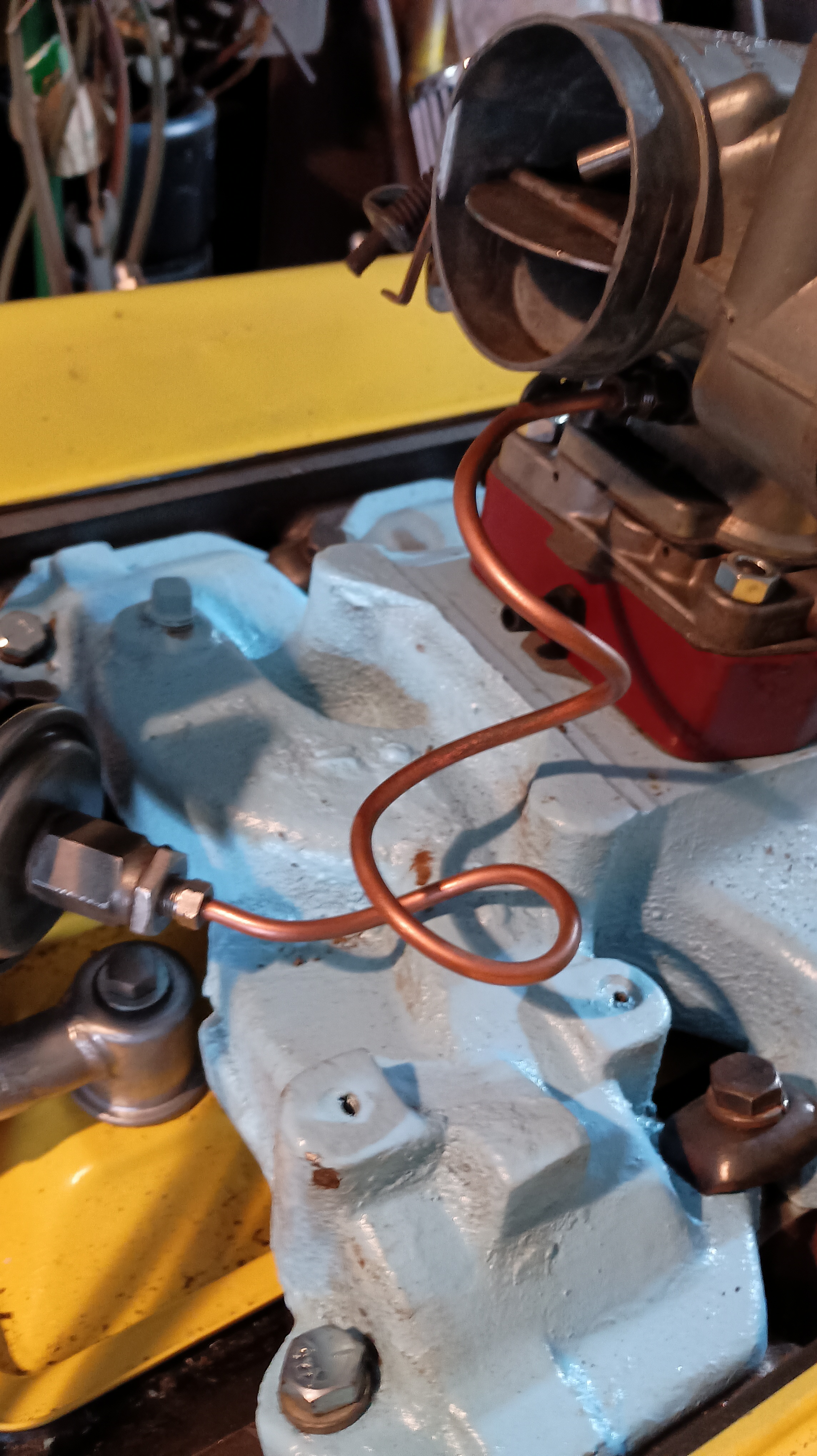
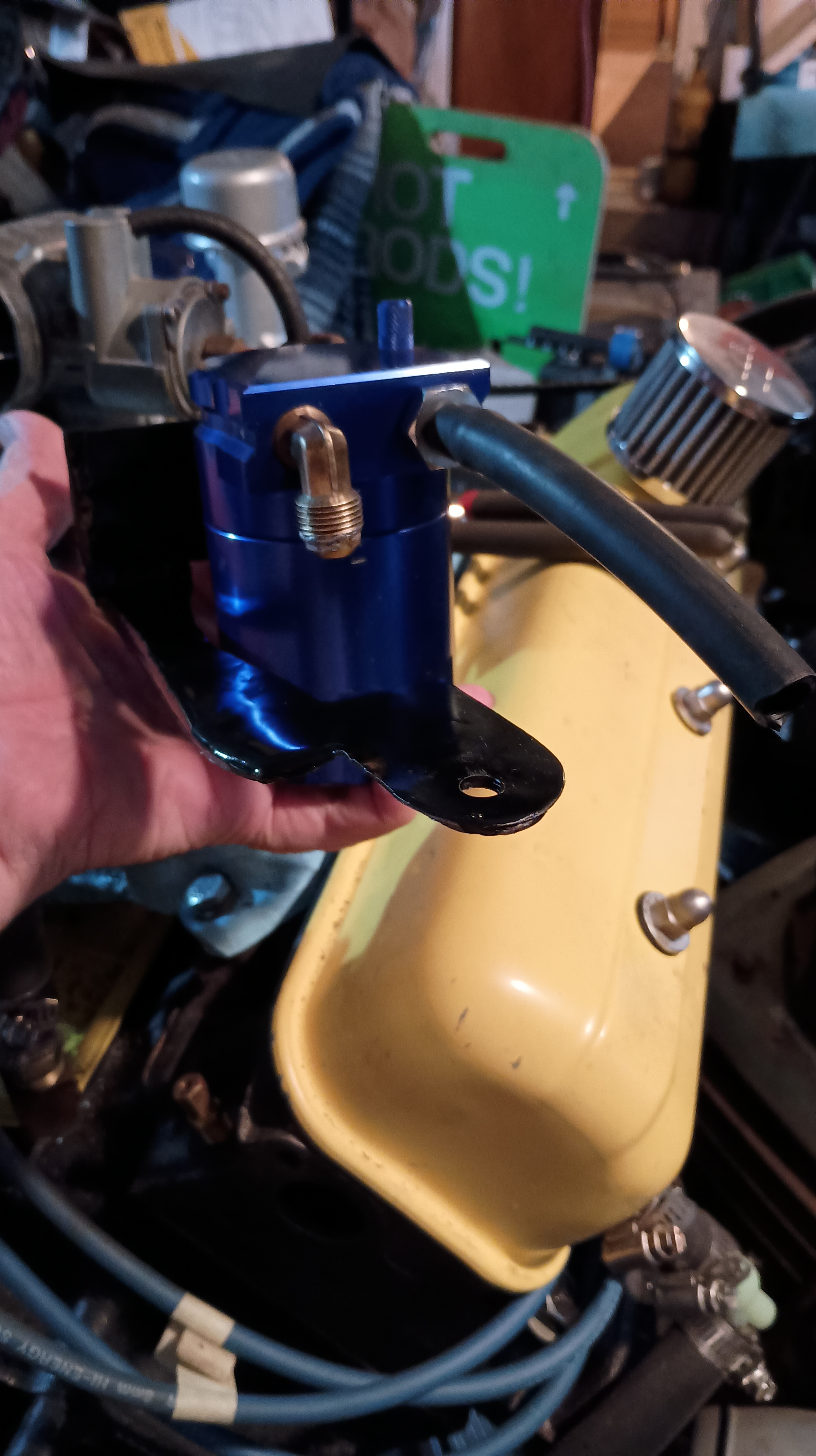
I received a partial exchange oil filter from Bob W. and have plumbed it in at the front of the engine. High pressure comes in through a passage at the front of the driver’s cylinder head. I placed a 0.050″ restrictor there. 3/16″ brake line was used to bring pressurized oil into the “outer” inlet into the filter base. The oil exits through the center hole in the base and then into the oil filler tower to return to the bottom of the engine. I was careful to avoid interference with the intake manifold location. I mocked up the bends of the 3/16″ line with wire and used 8″ lines. Looks like a 289 Ford filter works.


After some mixing and matching of available stuff from two wiring kits I assembled a radio suppression 8mm loom after determining that the 7mm solid core wires I ordered would upset the Pertronix distributor.

I mounted a painted intake manifold, carb and gaskets for a test fitting. The flywheel is back from a haircut from 39.5# to 26.5#. Made an axle/bearing setup to bolt solidly to use for static balancing….


This setup worked ok for balancing the flywheel itself consistently, but when I added the pressure plate assembly, it sagged to the point of being impractical. I will take the assembly off to a machine shop.
I found that shouldered ARP bolts from an early seventies Ford would be good replacements for originals.

After some eyeballing I determined that with a little trimming of the one wire Delco alternator, I could modify the hefty bracket from the old generator to work. Here is where I trimmed the alternator with the band saw….

I will replace the pivot with a 2.5″ bolt. The lower bracket turned out nice and strong…


I used a piece of string to approximate the size of the fan belt. I modified the adjustable top bracket from the generator to complete the alternator install.


Valuing my feet, and given the mods to the flywheel (and higher rpm likely to result), I felt that the initial scatter shield used at Bonneville should be modified for the v8 and used with this engine. Here is the shield as it exists. I will bend the bottom out a bit and add a lower bolt on section….
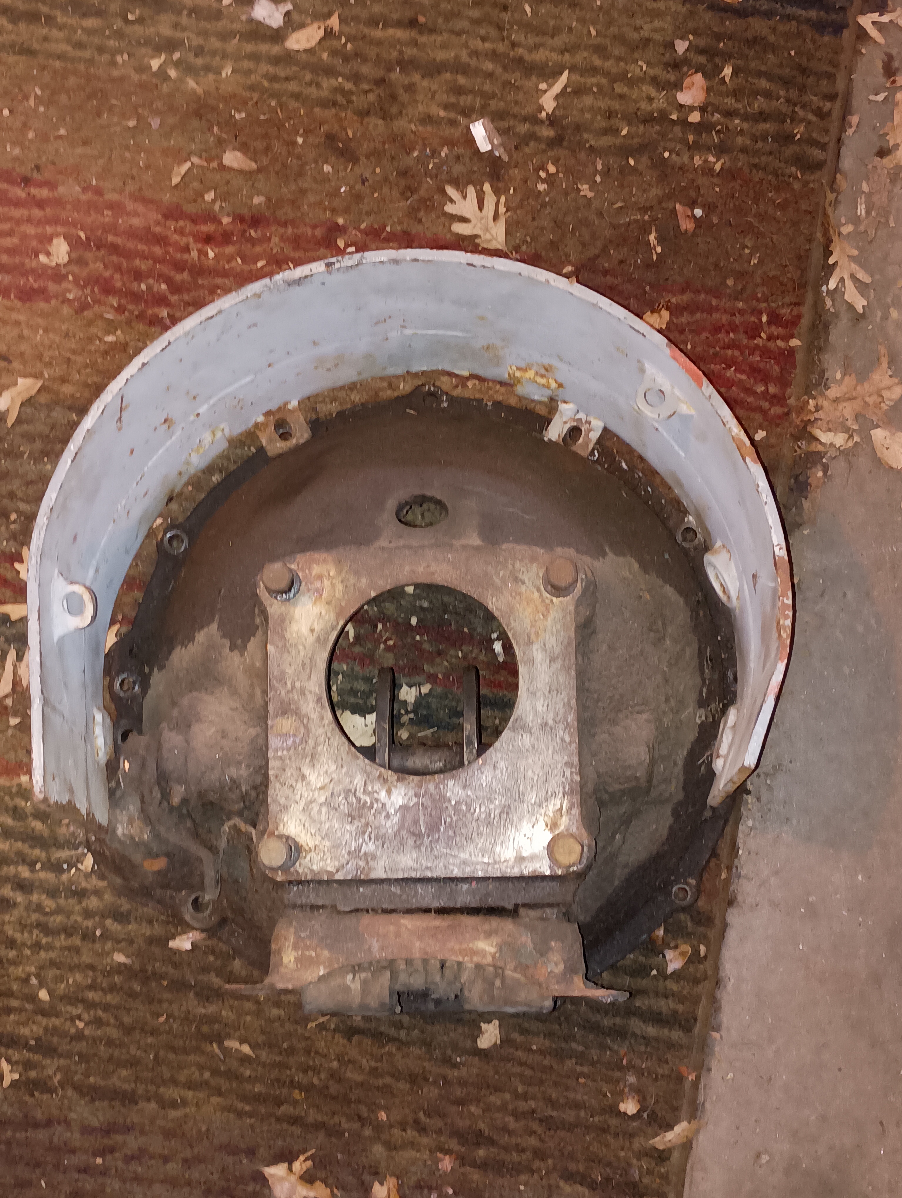

The red is a welded extension to the upper part. The purple can be a flat piece bolted across the bottom.
Looks like for now I will be using a 63′ intake manifold along with a Stromberg WE carb. To minimize vapor lock and increase torque, I developed a wooden carb spacer and painted it with Glyptal to prevent fuel from soaking it. I used a piece of solid maple. I added a nipple to reintroduce the exhaust gasses. I may add a tube with tiny orifices for water injection in the future.


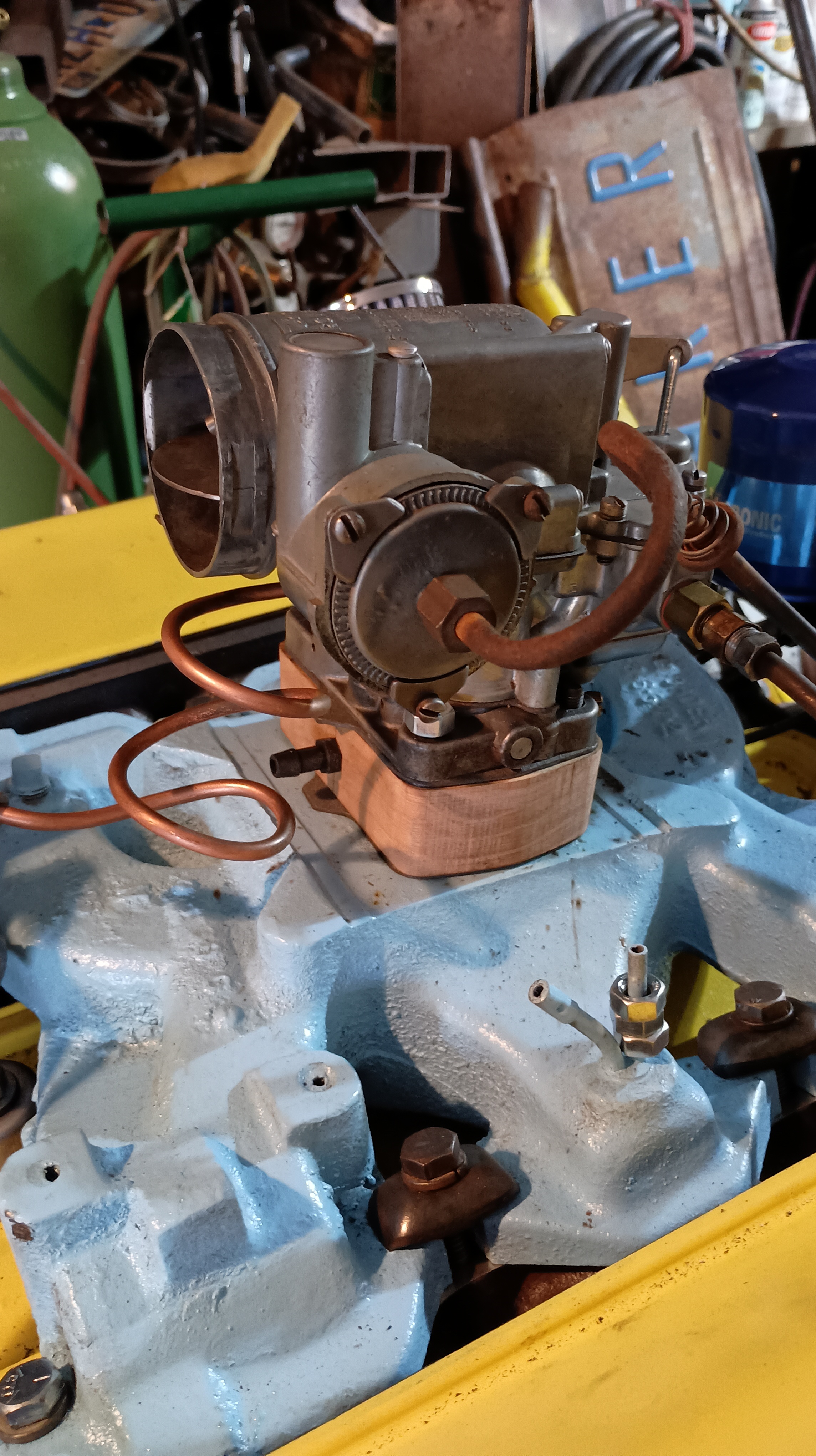

The carb is now installed with extra long bolts and hooked up to the automatic choke as well as the vacuum line to the distributor.

Completing the oil vapor recirculation system meant directing it out what was formerly the road draft tube on top of the lifter chamber into a catch-can and then through another PCV valve (Standard V 329) before entering the intake below the carb. I plumbed that up and made a bracket to hold the whole thing in place….


The engine is now assembled, but needs run-in oil added.
Now is time to build an engine stand. I have some industrial rollers, an aluminum gas tank, steel stock, a radiator and some gauges. The clutch/flywheel/pressure plate and starter motor are refurbished and ready to install. I have made brackets for the front motor mounts:

The rear mount is on the bottom of the scatter shield.
