Chapter 42: Boat-tail part 2 and explaining front suspension
Adding the sides to the boat-tail was less of a challenge than I thought! Maybe it’s all being intimidated by not having done it before, but actually, I have done all the little steps before, just not in this way. I cut out a template from paper which I confirmed should work on both sides and then used my pneumatic shear to cut out both sides…. a little bit wrong once I did some curving and bending! Then I had to add on a patch in the superior/anterior part of the panel. Bent the panel over a chunk of pipe and used the English wheel to get a nice compound curve near the rear. Very gratifying! Used the MIG on mostly “B” setting to creep along tacking down the panel. I find that to keep butt welds even a screw driver and body hammer are handy to raise or lower the adjacent panels. After welding it all on and filling in some gaps I was ready to grind it all flush. I have a lot of “hanger wire” which is like coat hanger but in 8 foot lengths normally used for hanging suspended ceilings. It works great to fill gaps in butt welds. Grinding it all flush was sped up by a new abrasive I just got for my angle grinder….60 grit in a flap wheel is really aggressive and by its nature better on curved surfaces than using something like a cut-off wheel or zip wheel. Here are the results of the driver’s side panel…. After adding the passenger side panel with hole for gas filler I will unbolt the works and do more finish bodywork up on some saw horses where I can get at the underside bracing etc.


FRONT SUSPENSION QUESTIONS
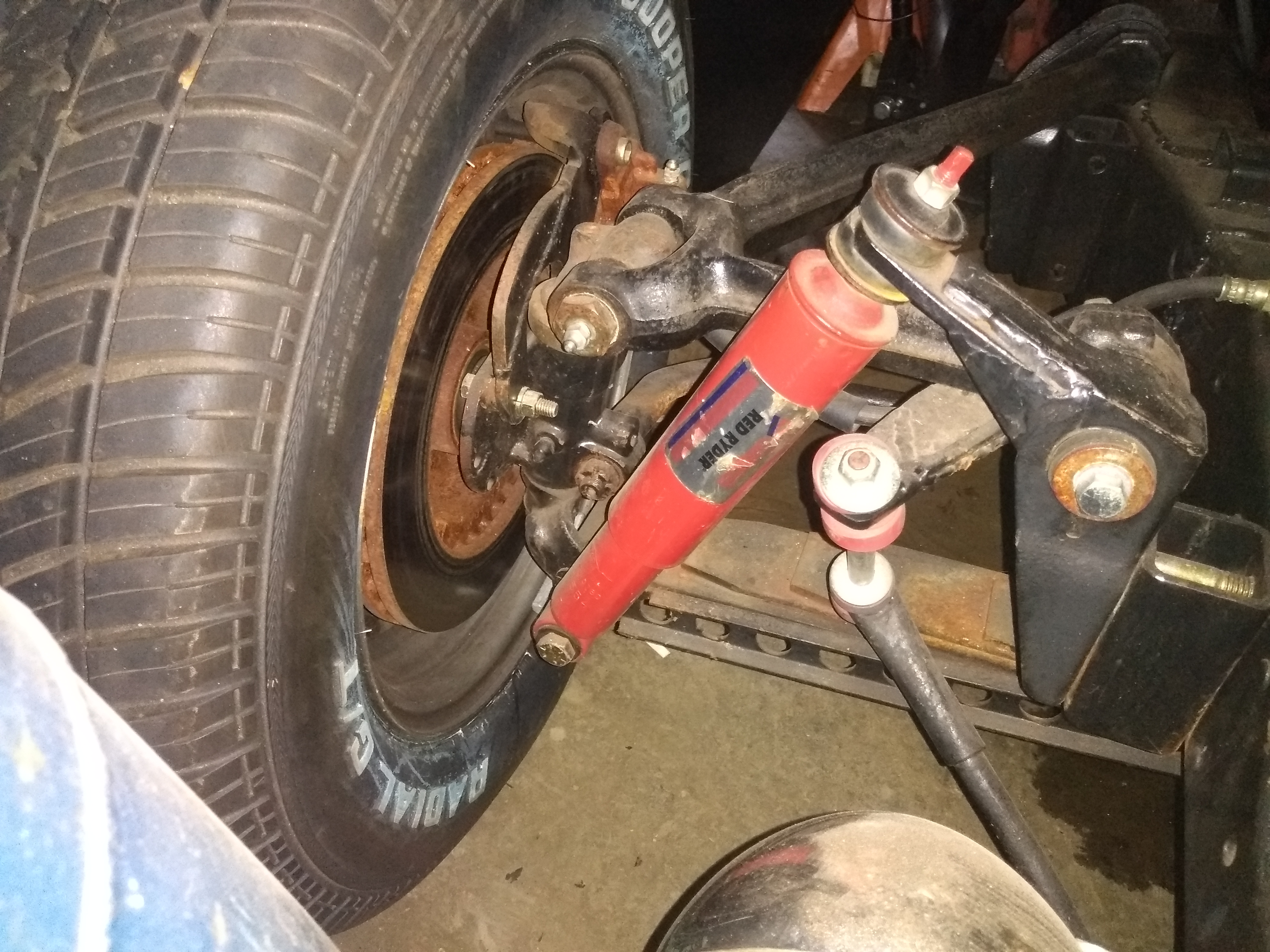
Some questions on explaining the front suspension came to me off the net… I used the frame from a 1941 Studebaker Commander for this project. It came two ways…. conventional beam type and as a PLANAR suspension. The planar was really started in 1936 and was kind of clunky looking, but by 41′ had a rather elegant cast upper a-arm. It used 12 leaf transverse leaves. Caster was minimally adjustable . Camber was adjusted with shims where the a-arms attached to the frame. It had Houdaille shocks. Though I never found a great explanation each side of the spring had a sheet metal bracket extending from the kingpin area to a slider a few inches lateral to the area where the spring was bolted down. This was missing on post-41 vehicles. I think it was there so that if the spring broke the front end wouldn’t collapse. The medial end slid along in a rubber bushing, so the bracket really didn’t affect handling. Since this was originally going to be built as a 3 wheeler with an engine from my race car, I wanted to widen the track to 63 inches. I used spacers and a leaf spring from a Chevy truck to add to the track. I made brackets for a modified 53′ Stude anti-roll bar which doubled as mounts for the Bronco telescopic shocks. Made adapter plates to hold Caddy disc brakes. Calculated and bent steering arms for tighter steering radius and attached Omni type rack and pinion (follower type) on custom bracket which I could adjust for minimum bump-steer. Front end tracks really well, NO roll, maybe 2″ of travel and no bump-steer. Handles about like a sports car rather than a race car. Steering radius is still not real tight but acceptable. Would be better if I were to take back the 4″ I added to track. No issue with having kingpins… went 140 mph in my 53′ coupe at Bonneville straight as an arrow!


Maybe in my next life I’ll make stuff look pretty……
